Modifiying a FDD for a Yamaha EL90
Disclaimer: use this information at your own responsibility. No responsibility is accepted by me for any damage as a result of using this information.
The information on this page is intended for users of a Yamaha Electone EL90 or EL70 organ with a broken diskdrive (MDR drive). In order to use this information you should have (basic) knowledge of electronics. You should also be able to use a solder-iron and you should be able to use a voltage-meter
Recently, I bought a Yamaha Electone EL90 organ. Used ofcourse. I was completely happy with it, until 3 days later: The MDR broke down, all of a sudden. The message in the MDR ‘display’ showed “Fort” (format) and “Bad”. None of the floppy’s could be read anymore. Also, writing and formatting didn’t work anymore. All it said was “Fort” and “Bad”.
I knew that an EL90 MDR wasn’t the same as a PC floppydrive. I remembered reading an article about that on Electone Zone. My drive’s problem was not a stuck spring which determines a HD or DD disk. My drive’s problem was that it was really broken. I had to look for a way to replace it.
I was lucky to find a webpage of Yvonne Sprenger (click here for that page) in which she explains her findings about the Yamaha MDR drive compared to a regular PC drive. That information eventually got me to modify a PC fdd so it could be used as an MDR drive. However, I made some changes in Yvonne’s setup, especially where a sensor signal needs to be inverted.
What needs to be changed?
- The flatcable has to put in reversed in the MDR controler
- The drive-select of the new FDD has to be set to “0” instead of “1”. This can be done by a twist in the flatcable, or by modifying the FDD
- The disktype (HD or DD) needs to be sent to the MDR controler on pin 2
- The signal “Disk Ready” needs to be sent to the MDR controler on pin 34
The information on this page may overwelm you and discourage you. Don’t let it discourage you. Most of the information is just background information. Please read it all and understand what the modification is all about. At the end you will see that the modifications aren’t that complicated.
Again, basically all this information was found out by Yvonne, so she deserves all the credits!! All I explain here is how I used her information to make it work in my drive:
Numbering of the interface
The pin-numbering of the MDR-controler (that is the circuitboard below the MDR bracket) is reversed compared to regular (PC) floppydrive interfaces. You can tell, because at the MDR-controler, the blue (or red) wire of the flatcable goes to pin 1. But at the floppydrive’s end of the cabe, this blue/red wire goes to pin 34: The numbering on the controler board should be reversed: 1 should be 34, 34 should be 1. (So, the floppy connector numbering is correct, the MDR controler isn’t).
Original (PC) Floppy pinouts
I searched the internet for the pinouts of a standard PC floppy diskdrive and found the following table: (source)
| 34 | /DSKCHG 1=Disk Change/0=Ready | 33 | GND (vss) |
| 32 | /SIDE1 0=Head Select | 31 | GND (vss) |
| 30 | /RDATA Read Data | 29 | GND (vss) |
| 28 | /WPT 0=Write Protect | 27 | GND (vss) |
| 26 | /TRK00 0=Track 00 | 25 | GND (vss) |
| 24 | /WGATE Floppy Write Enable, 0=Write Gate | 23 | GND (vss) |
| 22 | /WDATE Write Data | 21 | GND (vss) |
| 20 | /Step 0=Head Step | 19 | GND (vss) |
| 18 | /DIR 0=Direction Select | 17 | GND (vss) |
| 16 | /MOTEB 0=Motor Enable Drive 1 | 15 | GND (vss) |
| 14 | /DRVSB Drive Select 0 | 13 | GND (vss) |
| 12 | /DRVSB Drive Select 1 | 11 | GND (vss) |
| 10 | /MOTEA 0=Motor Enable Drive 0 | 9 | GND (vss) |
| 8 | /Index 0=Index | 7 | GND (vss) |
| 6 | N/C Reserved | 5 | GND (vss) |
| 4 | N/C Reserved | 3 | GND (vss) |
| 2 | /REDWC Density Select 1=Low/0=High | 1 | GND (vss) |
If I’m correct, this is from the PC controller point of view. The PC floppy drive’s pinout maybe a little different (specs of a Sony MPF920-E 1.44-MB Diskette Drive):
| 34 | /DSKCHG 1=Disk Change/0=Ready | 33 | GND (vss) |
| 32 | /SIDE1 0=Head Select | 31 | GND (vss) |
| 30 | /RDATA Read Data | 29 | GND (vss) |
| 28 | /WPT 0=Write Protect | 27 | GND (vss) |
| 26 | /TRK00 0=Track 00 | 25 | GND (vss) |
| 24 | /WGATE Floppy Write Enable, 0=Write Gate | 23 | GND (vss) |
| 22 | /WDATE Write Data | 21 | GND (vss) |
| 20 | /Step 0=Head Step | 19 | GND (vss) |
| 18 | /DIR 0=Direction Select | 17 | GND (vss) |
| 16 | /MOTOR ON 0=Motor Enable | 15 | GND (vss) |
| 14 | NOT CONNECTED | 13 | GND (vss) |
| 12 | /DRVSB Drive Select 1 | 11 | GND (vss) |
| 10 | /DRVSB Drive Select 0 | 9 | GND (vss) |
| 8 | /Index 0=Index | 7 | GND (vss) |
| 6 | N/C Reserved | 5 | GND (vss) |
| 4 | N/C Reserved | 3 | GND (vss) |
| 2 | NOT CONNECTED | 1 | GND (vss) |
This is a piece of schematics from the EL90 service manual. It shows the controler-floppy connector with numbering and signals:
Since we know that the numbering of the Yamaha controler is reversed compared to a PC floppy controler, I modified the numbering in the schema so it makes more sense:
So what needs to be done: Turn the connector at the controler-side so that the blue/red wire goes to pin 34 (which, as we know now, is electronically pin 1). If it doesn’t go in because of the thickning in the middle of the connector, use a sharp knife to remove that plastic there (carefull!). Obviously you can use a new connector if you want. Now you know that the floppy end of this cable has the right numbering: the coloured wire should go to pin 1 on the FDD.
It now (mostly) matches with the signals of a PC drive. There are still a few ‘buts’ however:
- 1. The original Yamaha MDR responds to drive-select 0 (at pin 10), a standard PC drive respons to drive-select 1 (at pin 12)
- 2. The signal for the MDR controler at pin 34 (Ready) is different than that signal of a PC drive (Disk Change)
- 3. The signal for the MDR controler at pin 2 (Disk) is probably not abailable on pin 2 of the PC drive
1. Changing drive select
In fact, pin 10 and pin 12 at the floppy connector needs to be switched. This can be done in 2 ways:first method: look closely on the circuitboard of the PC drive for jumpers which determin the drive select number. If it’s there it will have a text written next to it like ‘SEL0’ and ‘SEL1’. In the original situation, SEL1 (drive 1) has been connected (jumpered) and SEL0 (drive 0) has not. The image below shows this. Please note that this image is of a Sony MPF920 floppy drive. With other brands/models the drive select implementation may be different.
You can see a tiny SMD bridge (0 ohm resistor) at JC31. At JC30 (SEL0) there is a gap. The bridge at JC31 connects pin 12 to the chip (drive select). This is the default for PC drives, but the Yamaha MDR controler selects the drive at pin 10 (drive 0). So JC31 needs to be open and JC30 needs to be closed: The SMD at JC31 needs to be moved to JC30. This is a delecate procedure when you use a soldering tool! I suggest you remove (by soldering) the SMD and solder a wire at JC30 instead of the SMD component. The SMD component is just too small, a wire has the same effect.
second method: You can make the switch in the flatcable. Disassemble the connector at the floppy’s end, and split the cable between pin 9 and 10, and between 12 and 13 (remember, the coloured wire is pin 1). You now have 3 wires (10, 11, 12) which you have to flip :
Now wire 10 goes to pin 12, wire 12 goes to pin 10 and wire 11 remains at pin 11. The MDR controler will do a drive select at pin 10, which will be received at pin 12 of the floppy drive (drive 1) which is ok now, since the drive is set to be selected as drive 1.
Detailed information about changing the connector and twisting the cable
I used a PC floppydrive cable so I could leave the original EL90 cable unchanged
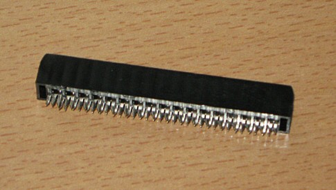
Open the connector. You need a small screwdriver. Bend both sides of the clips so you can disassemble the connector:
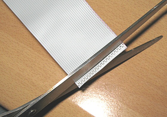
I removed all wires, cut off 1 cm of the end of the cable (to get a fresh new end without gaps) :
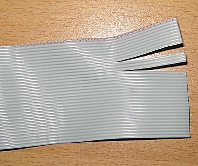
I split between wire 9 and 10, and between 12 and 13, so you have 10,11 and 12 seperated from the rest:
Then, twist the cable: 12 becomes 10, 10 becomes 12, 11 remains 11:
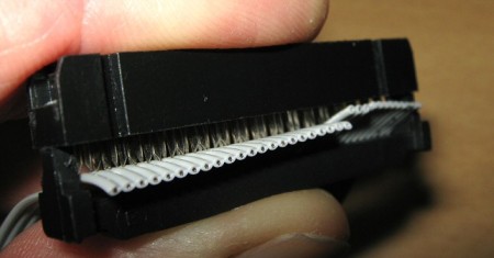
Put the cable PERFECTLY alligned in the connector’s contacts. Check. DOUBLE check.
Put the plastic end of the connector on top , keep all in place:
You need a tool (pincer) to set the cable on the connector’s contacts: Be gentle and patient, don’t force. When all is set, I advice you to use a measuringmeter to check of the contacts are ok.
Obviously, you could do without all this by cutting wire 10 and 12 within the flatcable, switching them around and soldering 10 to 12 and 12 to 10. That will work too and you don’t have to disassemble and re-assemble to connector, but it isn’t as nice.
Use just one of the two methods (switch device on the drive OR twist the cable), not both, since doing both will eventually reverse the process again.
Modifying the signal at pin 34
The MDR controler needs to know at pin 34, if the drive is ready. But the PC drive will use this pin to signal that the floppydisk has been changed. To correct this:
- Cut the original wiring at pin 34 on the circuitboard of the PC drive
- Get the correct signal (ready) from the ‘disk inserted’-switch of the PC drive
Cut this circuitwire at the circuitboard with a sharp knife. Be carefull and don’t cut any nearby circuitwires. The image shows it (badly) since the cut is underneath the grey wire. You can still see the scratching on the circuitboard however:
The following part requires you to do some measuring at the floppy switches. You can do that by supplying voltage to the drive and measure what happens at the switches when you insert a floppy. You could do without measuring and do this based on trial and error but I recommend that you measure the voltage so that you know what you’re doing.
On the circuitboard of the floppydrive, there are 3 switches which repond to “floppy available”, “write protect” and “high density/double density”. You need the switch “floppy available”. This one is next to the “write protect” switch:
Measure at the floppy in/out switch and note down what happens when a disk is in or out. If the disk is in, it should measure 0 volt. If the disk is out it should measure 5 volt. if this is the case you can solder a wire from that switch directly to pin34 of the of connector:
If this is the other way around (floppy in 5 volt, floppy out 0 volt) use an invertor between the switch and the connector (see below).
Modifying the signal at pin 2
Pin 2 of a PC drive is usually unused. In some interface implementations however, this pin may already be connected and act appropriate. Check this by looking closely to the circuitboard and measuring at Pin 2 of the connector. If there is a signal at pin 2 already, maybe you’re lucky and this modification is not necessairy. High Density floppy should measure 0 volt, Double Density floppy should measure 5 volt. If you measure it the other way around, you’ll have to use an invertor (see below). If you don’t measure correct values at pin 2, cut the circuitwire of pin 2 (if used), measure at the switch to make the modifications:At pin 2, the MDR controler wants to know the density of the floppy: High denity or Double density. The drive can tell because of the gap (or not) in the floppy disk. Gap means high density, no gap means double density. This switch is on the other side compared to the ‘write protect’ switch and ‘floppy in/out’ switch:
Insert a DD floppy and measure at the switch: It should be 5 volt;
Insert a HD floppy and measure at the switch: It should be 0 volt;
If you measure it the other way around, you’ll have to use an invertor (see below)If the signal is correct, solder a wire between the switch and pin 2. Your drive should now be ok to use with your EL90 / EL70.
Using an invertor
As discussed earlier, the following signals are needed:
Density-sensor at pin 2: DD-Disk: 5V, HD-Disk: 0V
Disk-ready-sendor at pin 34: Disk in: 0V, Disk out:5V
In my example I use the Sony MPF920 FDD. The density-signal has to be inverted. At Yvonne Sprenger’s page, she uses a transistor to accomplish this. This may have worked in her situation, but it didn’t in my setup. I have to confess that I used another transistor, but that should not be a problem. However, I decided to use a IC component for this: a 74LS00. This one component houses 4 possible invertors in one IC. You might need two invertors, so you just need one 74LS00.Connect pin 1 with 2. This is now one input. Pin 3 is the inverted output of this.
Connect pin 4 with 5. This is now also one input. Pin 6 is the inverted output of this.
Connect pin 7 to ground and pin 14 to +5V. You’re set to go:
In my example I need to invert the signal of the density sensor before it goes to pin 34 of the drive’s connector. Solder a wire from the sensorswitch and solder it to pin (1+2) of the IC. Solder another wire at pin 3 of the IC which now goes to pin 34.
The 0 V at the input of the IC will now become 5V at the output and vice versa.
I sticked the IC on a bare part of the drive (see image above). I used doublesided sticky tape. This stuff glues perfectly. Double check that none of the IC’s pins can touch anything else of the drive. Before closing the drive with its cover (if any), put tape on the inside of the cover to avoid pins of the IC directly touching the cover (which is ground and could shortcut).
Chances are that your drive will have a green LED, the original MDR has a red LED. I’m a bit of a perfectionist so I replaced the green LED by a red one.
Now you can reinstall the controler and drive. Test with the EL90 still open so you can go back to the drawingboard if it doesn’t work yet.
Once your new MDR is up and running you will probably notice that the drive’s LED is continiously on. That is a “feature” of the floppy drive. It doesn’t affect the operating of the drive.
Thanks to Yvonne Sprenger for providing this information which made it possible for me to get my EL90 fully functional again and make a little enhancement to the original modification. I hope this page helps other EL users to fix their MDR.


Hello
Thanks for posting this. I have a Yamaha US1 that came just before the EL series. I am told that it used an MDR2
Do you know if this method would enable me to substitute a PC floppy drive as my MDR refuses to work!
Geoff
Isn’t the US1 the same as an HX-1? Did it come with built-in drive?
I can’t tell whether or not the described procedure works for your US1. You could try to open up the drive and check the cables and interface by doing some measurement. At your own risk 😉
thank u for this valuable information
hope to get an EL90 soon
He, it looks that we’ve both invented the wheel 😉
Take a look at our (not finished) website, almost the same info.
Kind regards,
Yvonne Sprenger
Hello Yvonne,
It is based on your information. I just made a variation on the invertor. The rest is the same.
Thanks for that information by the way, I could repair my EL90 with that!
Ton
Hello
The DFF of my EL-900m is broken too 😦
Is it the same process to transform EL-90 and EL-900m FDD ?
Is there a way to convert USB to floppy connector, this will allow us to use USB drive instead of floppy ?
I expect it to be the same drive, since the EL900 and EL90 relate to eachother. I’m not sure however, since I don’t have an EL900(m).
Hi,
I tried 3 disc drives, even the same type of your
description, but none of them worked.
Put the cable 1>34 at the floppy side, no reaction at all. Put the cable 1 > 1 the led goes on and the drive reacts at floppy’s, but even doesn’t work.
The original drive gives the BAD sign and asking for Format. The strange thing is, I can record and play myself and read and install the registrationfloppy I got with the organ; but registration floppy’s from another organ are denied.
No other way then buy an original drive…..
Ton – your method works fine for the EL70 – Ihave just finished your modification and the new floppy drive works in the EL70. The problem for me was that the integrated circuit you specified 74ls00 is no longer available in our local store and I did not understand the numbering. Once I worked out it is a NAND gate, I found that a 74HC00 could substitute, but that the 74ls02 is a NOR gate, which must not be used.
Thank you very much for your detailed method which has been invaluable.
David
Thx for the details step.
What about if my model is EL-100 ?
This alteration can apply to it.
very helpful info david, thanks
I bought a floppy drive emulator on ebay.
It simulates 100 disks with 1 usb stick.
My EL90 Controller and drive were NOT reversed – iirc – but that part confused me completely…
There was a jumper to set it to drive-select0, and pin 2 seemed to be no problem.
Strangely, it worked in a Computer AND with the EL90, without changing pin 34.
What I’m trying to figure out atm is, how to let me switch to the next disk, as the controller accesses the drive continuously and during access, I may not change disk.
Also the power cable was too short.
Thanks a lot for these informations.